Offcanvas top

9 Common Causes of Flange Leaks in Piping Systems

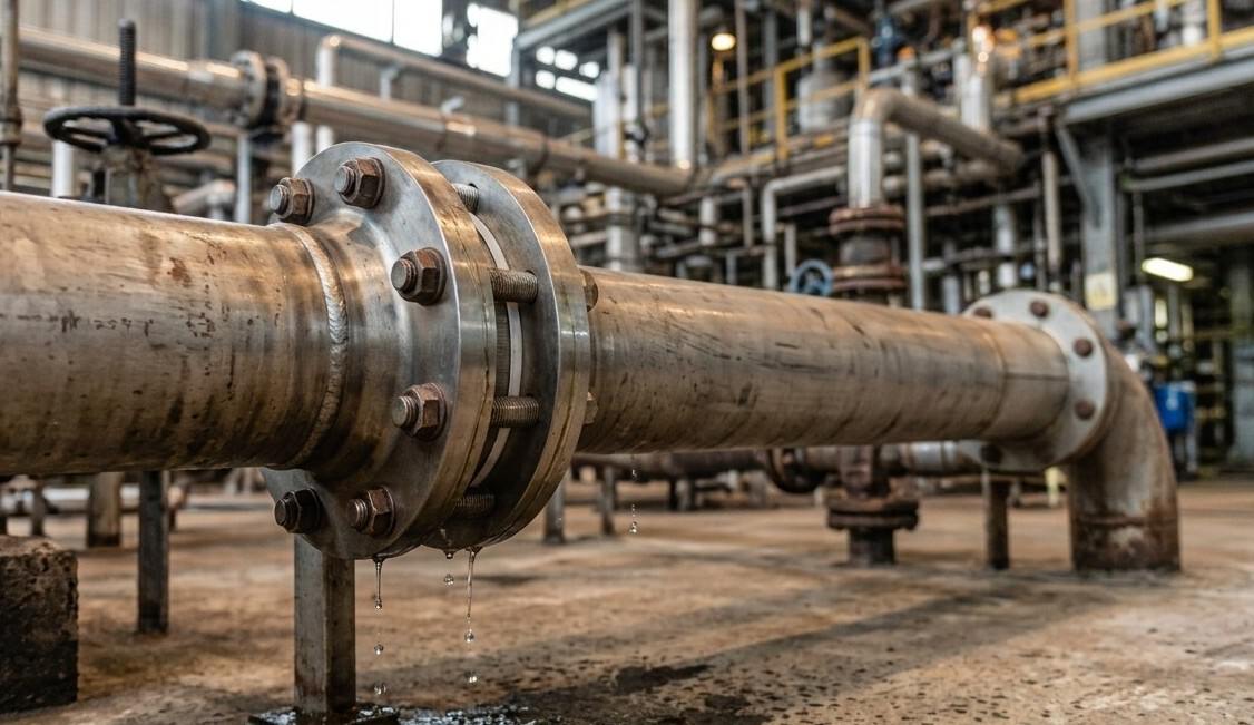
Flange leaks are one of the most common problems piping teams deal with in oil and gas, petrochemical, and construction projects. A leak might start small, a faint drip or a hint of moisture, but if the root cause isn’t fixed, it usually gets worse and can lead to downtime or safety issues.

The good news is that almost every flange failure traces back to one of a small, repeatable set of 9 causes of flange leaks. Once you know what to look for, they’re fairly easy to prevent.

A flange only seals properly when the gasket is compressed evenly between two flat, clean surfaces. When that balance is disturbed, even slightly, a leak path can form. Below are the 9 causes of flange leaks that piping teams run into most often.

1. Uneven Bolt Tightening

When some bolts carry more load than others, the gasket compresses unevenly around the flange. That imbalance creates a low-pressure zone where fluid or gas can start to seep through.

2. Misaligned or Non-Parallel Flange Faces

If the two flange faces aren’t parallel, the gasket gets crushed on one side and left loose on the other. This is one of the more overlooked causes of flange leaks because the joint can look fine from the outside.

3. Off-Center Gasket Installation

A gasket that isn’t centered on the bolt circle won’t compress evenly. Part of the gasket ends up overloaded while the rest barely seals at all.

4. Dirty, Scratched, or Corroded Flange Faces

Pitting, scale, weld spatter, or old gasket material left on the sealing surface all create tiny leak paths that no amount of bolt torque can close.

5. Excessive Piping Loads on the Joint

When pipework isn’t properly supported, weight from valves, fittings, or the pipe run itself gets transferred straight into the flange, bending it slightly and reducing gasket contact.

6. Wrong Gasket Size or Material for the Job

A gasket that’s the wrong size is usually caught during installation, but the wrong material for the fluid, pressure, or temperature often isn’t caught until it’s already leaking, or worse, corroded through.

7. Sudden Temperature Swings

Rapid heating or cooling causes flanges to expand or contract unevenly, warping the joint slightly and loosening bolt stress at the worst possible moment.

8. Excessive Vibration From Nearby Equipment

Pumps, compressors, and other rotating equipment can shake bolts loose over time, even if the joint was torqued correctly at installation.

9. Reusing an Old Gasket

Once a gasket has been compressed and the joint opened, it has already lost the material properties it needs to seal again. Reusing it is one of the most avoidable causes of flange leaks.

Any one of these on its own can start a leak. In real-world cases, it’s often two or three of them working together, for example, a slightly misaligned flange combined with uneven bolt tightening.

Cause and Fix at a Glance

#Common CausePractical Fix
1Uneven bolt stressTighten bolts in a crisscross pattern using a calibrated torque wrench
2Misaligned flange facesCheck parallelism before bolt-up and correct alignment
3Off-center gasketUse a gasket sized to seat evenly against the bolt circle
4Damaged flange facesClean and inspect surfaces before every reassembly
5Excessive piping loadsEnsure proper support and flexibility in the piping design
6Wrong gasket material or sizeMatch the gasket to the fluid, pressure, and temperature
7Thermal shockRecheck bolt tension after temperature stabilizes
8High vibrationAdd damping and recheck bolt tension on a schedule
9Reused gasketAlways install a new gasket at reassembly

Steps That Actually Prevent Repeat Leaks

Most experienced piping teams follow a fairly consistent process once a joint has leaked more than once.

  • Inspect the flange face for pitting, scratches, or warping before reassembly
  • Confirm the gasket is centered and the correct size for the bolt circle
  • Hand tighten bolts first, then torque them in stages using a crisscross sequence
  • Recheck bolt tension after a short run in period, especially on new installations
  • Keep records of any joint that leaks more than once, since repeat failures usually point to a design issue rather than a one time mistake

Skipping any of these steps is usually how a joint ends up back on the maintenance list within a few months.

Choosing the Right Flange for the Job

The flange itself plays just as big a role as the gasket. A weld neck flange handles high pressure and cyclic loading well, while a slip on flange is easier to install where precise pipe length isn’t critical. A blind flange is used to seal the end of a pipe run completely, and a socket weld flange suits smaller diameter, high pressure lines where a strong weld is needed.

Using a flange that isn’t rated for the actual service conditions is one of the quieter causes of flange leaks, since the problem often doesn’t show up until the system is under real pressure.

A Quick Word on Safety

Flange leaks aren’t just a maintenance inconvenience. In high pressure or high temperature systems, a sudden leak can put people at risk and cause serious damage to nearby equipment.

Regular inspection, correct torque procedures, and using the right materials from the start go a long way toward keeping a plant both efficient and safe.

Conclusion

Stopping the 9 causes of flange leaks for good comes down to getting the basics right every time. Correct bolt tightening, proper flange alignment, clean flange faces, and a gasket that actually matches the service conditions will prevent most of the leaks that plague piping systems.

Fitting World Trading LLC supplies a wide range of flanges and gaskets built for demanding piping applications across Dubai, the UAE, and the GCC.

Ready to get started? Reach out to our team today for technical advice or a fast quote..

Best Selling Products

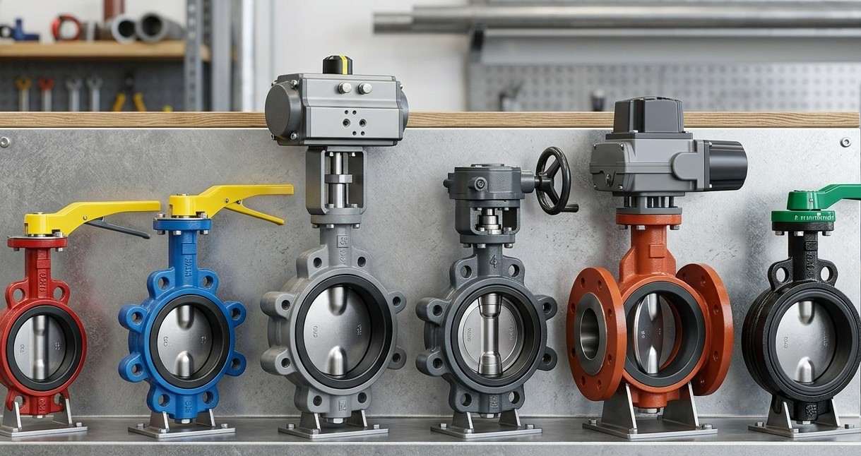
Butterfly Valves: Types, Uses & Benefits Guide

Butterfly valves are widely used in water supply, HVAC, chemical processing, food processing, power generation, and industrial piping systems. Their compact design, simple operation, and suitability for large pipe sizes make them a practical choice for many flow control applications.

A butterfly valve uses a rotating disc to control or stop the movement of liquids, gases, and other media. The disc rotates around a shaft, allowing the valve to open, close, or regulate flow. As a quarter-turn valve, it typically rotates 90 degrees between fully open and fully closed positions.

What Is a Butterfly Valve?

A butterfly valve is a rotary valve designed for flow control and isolation. Its main components include the valve body, disc, stem, and seat.

When the valve is fully open, the disc turns parallel to the flow, creating a relatively open passage. When closed, the disc rotates against the seat to stop the flow.

The compact design of butterfly valves makes them useful in systems where installation space is limited. Wafer butterfly valves, for example, are installed between pipe flanges and require less space than many conventional valve designs.

How Does a Butterfly Valve Work?

The operating principle is simple. A handle, gearbox, pneumatic actuator, or electric actuator rotates the valve stem, which turns the disc inside the pipe.

  • Fully open: The disc allows maximum flow.
  • Partially open: The disc restricts flow.
  • Fully closed: The disc blocks the passage.

This quarter-turn operation also makes butterfly valves suitable for automated piping systems.

Main Parts of a Butterfly Valve

Understanding the main butterfly valve parts can help when selecting a valve.

  1. Valve body: Connects the valve to the piping system and houses the internal components.
  2. Disc: Rotates inside the pipe to control fluid movement.
  3. Stem: Transfers movement from the handle or actuator to the disc.
  4. Seat: Creates a sealing surface when the valve closes.
  5. Actuator: Provides manual or automatic operation. Common options include levers, gearboxes, pneumatic actuators, and electric actuators.

Types of Butterfly Valves

Different butterfly valve types are designed for different piping requirements.

Wafer Butterfly Valve

A wafer butterfly valve fits between two pipe flanges. Its compact design makes it suitable for installations where space is limited.

Lug Butterfly Valve

Lug-style valves have threaded lugs around the body. They are useful where sections of a piping system may need to be isolated or removed independently.

Flanged Butterfly Valve

Flanged butterfly valves connect directly to matching pipe flanges and are commonly used in larger industrial piping systems.

Double Offset Butterfly Valve

A double offset butterfly valve moves the disc away from the seat during much of its rotation. This reduces contact between the disc and seat and can help reduce wear.

Common Butterfly Valve Materials

Butterfly valve materials vary depending on the valve component and operating conditions.

Common body and disc materials include:

  • Cast iron
  • Ductile iron
  • Carbon steel
  • Stainless steel
  • Aluminium bronze

Common seat and lining materials include:

  • EPDM
  • NBR
  • PTFE

The appropriate combination depends on the fluid, pressure, temperature, corrosion requirements, and application. Always check the manufacturer’s specifications before selecting the valve.

Butterfly Valve Applications

Butterfly valves are used in many industrial and commercial systems, including:

  • Water treatment plants
  • Water distribution systems
  • HVAC systems
  • Cooling water lines
  • Fire protection systems
  • Chemical processing
  • Food and beverage processing
  • Power generation
  • Industrial process piping

Their lightweight and compact construction makes them particularly useful for large pipelines.

Advantages of Butterfly Valves

Butterfly valves offer several benefits:

Compact design: They require less installation space than many traditional valve types.

Lightweight construction: Their simple design can reduce weight, especially in large pipe sizes.

Quick operation: Quarter-turn operation allows fast opening and closing.

Easy automation: Pneumatic and electric actuators can provide remote operation.

Large size availability: Butterfly valves are widely available for large-diameter piping systems.

How to Choose the Right Butterfly Valve

Consider these factors before selecting a butterfly valve:

  1. Fluid type: Identify whether the valve will handle water, air, chemicals, slurry, or another medium.
  2. Pressure and temperature: Check the valve’s pressure-temperature rating.
  3. Valve size: Match the valve to the required flow rate and piping system.
  4. Material: Select body, disc, and seat materials compatible with the application.
  5. Connection type: Choose wafer, lug, or flanged construction based on the piping system.
  6. Actuation: Decide between manual, pneumatic, or electric operation.
  7. Flow control: If throttling is required, check the valve’s flow characteristics and sizing data.

Butterfly Valves vs Gate Valves 

Butterfly valves and gate valves are both commonly used for flow isolation, but they work differently.

A butterfly valve uses a rotating disc and operates with a quarter turn. A gate valve uses a gate that moves vertically to open or close the flow path.

Butterfly valves are generally more compact and lightweight, making them useful for large pipelines and systems with limited space. Gate valves may be preferred for applications requiring a full, unobstructed flow path when open.

Final Thoughts

Butterfly valves are a practical option for flow control and isolation in many piping systems. Their compact design, quarter-turn operation, and range of materials and actuation options make them suitable for different industrial applications.

When sourcing compatible piping components, a pipe fittings supplier in UAE such as Fitting World Trading LLC can help with product selection based on project requirements. For specific product or application questions, contact our team.

Expert Guides on Industrial Insights


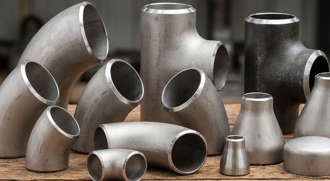
5 Critical Factors to Consider When Choosing Buttweld Fittings

Every piping system depends on the smallest connections to hold up under real pressure. Buttweld fittings are the parts that keep pipelines sealed, aligned and safe, whether the system is carrying crude oil, steam or process chemicals. Get the selection wrong and you are looking at leaks, corrosion and unplanned shutdowns down the line.

If you work in oil and gas, petrochemical, construction or marine projects across the UAE, you already know that fittings are not a place to cut corners. Below are the five factors that actually matter when picking buttweld fittings, along with practical guidance you can apply on your next project.

Material Compatibility With Your Piping System

The material of the fitting has to match the pipe and the fluid running through it. This single decision affects strength, corrosion resistance and how long the joint lasts once it is welded into place.

Most industrial projects use one of three material families.

  • Carbon steel works well for high temperature and high pressure lines where cost efficiency matters
  • Stainless steel resists corrosion and suits chemical processing plants and food grade systems
  • Alloy steel handles extreme temperature and strength demands found in refineries and power plants

Here is a quick way to compare the three at a glance.

MaterialBest Suited ForKey Advantage
Carbon SteelOil, gas, and general industrial pipingHigh strength at lower cost
Stainless SteelChemical, marine, and food processing linesStrong corrosion resistance
Alloy SteelHigh-temperature refinery and power systemsPerforms well under extreme heat

Choosing a mismatched material almost always shows up later as scaling, pitting or premature failure at the weld joint. If you need help matching a fitting grade to your pipe specification, browse the buttweld fittings supplier in UAE range for stocked material options.

Selecting The Right Fitting Type For The Application

Buttweld fittings are not one size fits all. Each type serves a distinct function in the piping layout, and picking the wrong one creates flow restrictions or unnecessary stress on the system.

The common types you will come across include

  • Elbows for changing pipe direction at 45 or 90 degrees
  • Tees for branching flow off the main line
  • Reducers for connecting pipes of different diameters
  • Caps for sealing the end of a pipeline
  • Stub ends for creating removable connections with lap joint flanges

For tighter layouts or where flow needs to stay smooth, long radius elbows are usually the better pick over short radius versions since they reduce turbulence and pressure drop. If you want a deeper look at how direction changing fittings perform in real systems, this guide on elbow pipe fittings types and applications breaks it down further.

Dimensional Accuracy And Industry Standards

A fitting can be made from the right material and still cause problems if the dimensions are off. Outer diameter, wall thickness and beveling all need to line up precisely with the pipe for a clean weld.

This is where recognized standards come in. Fittings manufactured to ASME B16.9 or ASTM specifications are tested for consistent dimensions, which makes welding faster and reduces the chance of leaks at the joint. Always confirm the pipe schedule as well, since fittings are sized to match a specific wall thickness and an unspecified schedule usually defaults to standard wall, which may not be what your project needs.

Getting the installation right is just as important as getting the sizing right. Our post on threadolet fitting installation best practices covers techniques that apply broadly to buttweld connections as well.

Pressure And Temperature Ratings

Every buttweld fitting has a working limit, and pushing past it is one of the fastest ways to compromise a piping system. The pressure rating depends on the wall thickness and material grade, so this factor ties directly back to your material and schedule choices.

Before finalizing an order, check the following

  • Pressure class rating against your system design pressure
  • Maximum allowable working pressure under operating conditions
  • Both the operating and design temperature range for the application

Underrated fittings do not usually fail immediately. They tend to develop stress cracks over months or years of cyclical pressure, which makes this factor easy to overlook during initial procurement. Safety critical components like valves face the same scrutiny, and our article on safety valve insights for UAE industrial processes explains why rated components matter across an entire system, not just at the fitting level.

Manufacturer Reputation And Quality Assurance

Even a perfectly specified fitting is only as reliable as the manufacturer behind it. Quality control separates fittings that perform for decades from ones that fail within a year.

Look for suppliers who provide

  • Third party testing and certified material test reports
  • Recognized quality certificates such as ISO 9001
  • Full traceability from raw material to finished fitting
  • Consistent stock availability and responsive after sales support

A supplier’s track record tells you a lot before you even place an order. Ask for documentation on past projects and check whether their certifications are current rather than expired. The same due diligence applies when sourcing other piping components, and our guide on factors to consider when buying industrial hose fittings walks through a similar evaluation process for hose based connections.

Comparing The Five Factors At A Glance

FactorWhat to CheckWhy It Matters
Material CompatibilityPipe and fluid compatibilityPrevents corrosion and scaling
Fitting TypeElbow, tee, reducer, or cap functionMatches flow and layout needs
Dimensional AccuracyASME or ASTM conformanceEnsures clean, strong welds
Pressure and TemperatureMAWP and design temperatureAvoids stress cracks and bursts
Manufacturer QualityCertifications and traceabilityReduces defect and failure risk

Final Thoughts On Choosing Buttweld Fittings

Selecting the right buttweld fittings comes down to matching material grade fitting type dimensional accuracy pressure rating and manufacturer quality to the actual conditions your piping system will face. Getting each of these factors right reduces leaks premature wear and unplanned downtime across oil gas petrochemical and construction projects.

Fitting World Trading LLC stocks a wide range of buttweld fittings built for demanding industrial piping applications across Dubai the UAE and the GCC.

Ready to get started? Reach out to our team today for technical advice or a fast quote.

Expert Guides on Industrial Insights

If you want to deepen your understanding of industrial equipment, material handling, and engineering best practices, explore these related articles.


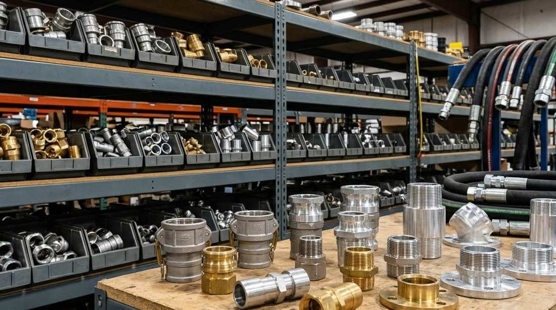
7 Factors to Consider When Buying Industrial Hose Fittings

Choosing the right industrial hose fitting affects how a fluid system performs over its entire service life. A fitting that is mismatched to the working pressure, media, or thread standard often leads to leaks, premature wear, or unplanned downtime long before the hose itself wears out.

Engineers, procurement teams, and maintenance managers who understand what actually separates a reliable fitting from a poor one can avoid most of these problems before installation even begins. This guide breaks down the practical factors that matter most when buying industrial hose fittings for hydraulic, pneumatic, or fluid transfer systems.

Material Selection And Corrosion Resistance

The base material of a fitting determines how well it holds up against the fluid it carries and the environment it sits in. Carbon steel suits general hydraulic circuits due to its strength and cost efficiency, brass works well in lower pressure air and water lines, and stainless steel is preferred for chemical, marine, food, and pharmaceutical use where corrosion resistance matters most.

Surface treatment also plays a role. Zinc or zinc nickel plating protects carbon and alloy steel fittings, while stainless steel relies on its natural chromium content instead of a coating. Fittings used in exposed marine or offshore environments face similar corrosion challenges to those covered in this overview of storm valves in marine industries.


Pressure Rating And Working Conditions

Every fitting is built around a working pressure range that should sit comfortably above the system’s actual operating pressure, leaving room for occasional spikes. A frequent mistake is confusing working pressure with burst pressure.

Working pressure is the level a fitting is designed to handle continuously, while burst pressure is the point of mechanical failure under test conditions. The two numbers should never be used interchangeably when planning a system.

MaterialTypical Working Pressure
BrassUp to 2500 psi
Carbon SteelUp to 3000 psi
Plated SteelUp to 4000 psi
Stainless SteelUp to 6000 psi
Alloy SteelUp to 10000 psi

These figures are general references, and actual ratings vary by fitting size and design, so checking the manufacturer’s documented pressure range for each product series is a more reliable approach than assuming values based on similar looking parts. Systems that also rely on pressure relief components can benefit from reviewing these safety valve insights for UAE industrial processes to understand how pressure management extends across a full piping system.

Size And Thread Type Compatibility

Correct sizing begins with matching the fitting bore to the hose inside diameter, then confirming the thread form matches the mating port on the pump, valve, or cylinder. Common thread standards include NPT, BSP, JIC, ORFS, and metric threads, each with its own sealing approach and regional prevalence.

Reading a fitting correctly means checking the outer thread diameter and pitch against a reference chart before ordering a replacement, since a mismatch here is one of the most common causes of cross threading and early leak points. For fittings that connect at odd angles or split flow between lines, this guide on elbow pipe fittings types and applications explains how directional fittings are sized and selected for real world piping layouts.

Connection Style And Sealing Method

The physical layout of a fitting affects installation ease and long term reliability. Straight fittings give a direct inline connection, elbows redirect flow in tight spaces, tees split or combine flow, adapters bridge different thread types, and couplings allow quick disconnection in lines serviced often.

The sealing method matters just as much as the shape. O ring, tapered thread, flare, and gasket seals each respond differently to vibration and thermal cycling, and a face seal design generally outperforms a tapered thread seal in circuits with frequent movement. Systems using grooved connections for quick assembly can benefit from reviewing this guide on grooved pipe fittings types and installation.

Temperature Range And Media Compatibility

Temperature affects both the fitting body and the seal material inside it. Hydraulic oil circuits, compressed air lines, and chemical transfer systems each present different combinations of ambient and internal media temperature, and the seal chosen should tolerate both extremes the application is likely to face.

Seal MaterialApproximate Temperature RangeCommon Use
Nitrile-40°F to 250°FGeneral hydraulic oil and water-based fluids
Fluorocarbon-15°F to 400°FHigher heat and chemical-resistant applications
PTFE-100°F to 500°FWide chemical resistance and broad temperature range

Media compatibility extends beyond temperature alone. Certain hydraulic fluids and cleaning chemicals interact with elastomers over time, causing the seal to swell or harden well before the fitting body shows visible wear, which is why seal material deserves the same scrutiny as the metal fitting itself.

Manufacturing Quality And Installation Practice

Manufacturing method influences how consistently a fitting performs under repeated pressure cycling. Forged fittings generally have a denser internal grain structure than cast fittings, supporting more even stress distribution around the thread and sealing surfaces.

Surface finish quality, including consistent plating thickness and smooth sealing faces, also affects corrosion resistance and how well the fitting maintains a tight seal across repeated assembly cycles. Correct installation practice matters just as much as the fitting itself, since even a well made part can fail early if assembled incorrectly.

Reviewing established guidance such as these best practices for threadolet fitting installation offers a useful reference for the kind of care that extends service life across threaded and branch connections alike.

Availability And Delivery Timelines

A fitting that meets every technical requirement is still a problem if it cannot be sourced when a project needs it. Lead time becomes especially important for facilities that run continuous operations, where a single missing fitting can hold up an entire maintenance window or installation schedule.

Buyers should confirm stock availability, minimum order quantities, and typical delivery timelines before committing a project schedule to a specific fitting configuration. Suppliers who carry consistent inventory across common sizes and thread types reduce the risk of last minute substitutions that were not part of the original design.

Supplier Reliability And Support

Even a well specified fitting depends on consistent production quality to perform as expected. Working with a supplier that maintains stable dimensional tolerances across production batches reduces the risk of fit issues when components from different orders are installed together, which matters most in facilities that source and maintain equipment over many years.

Custom requirements are common in industrial settings, particularly where equipment uses non standard port sizes or unusual routing geometry. A supplier able to adjust bend angles, thread combinations, or overall length gives engineering teams more flexibility than working from fixed catalog sizes alone.

Buyers comparing hose and fitting assemblies for hydraulic or pneumatic systems can browse a full range through this Industrial Hoses Supplier to match products against project specifications before ordering.

Conclusion

Selecting the right industrial hose fitting comes down to matching material, pressure rating, thread type, sealing method, temperature range, manufacturing quality, availability, and supplier reliability to the actual working environment. Getting each of these factors right reduces leaks, premature wear, and unplanned downtime across hydraulic and fluid transfer systems.

FW Trading LLC stocks a wide range of industrial hose fittings built for demanding hydraulic and fluid transfer applications across Dubai, the UAE, and the GCC.

Ready to get started? Reach out to our team today for technical advice or a fast quote.

Expert Guides on Industrial Insights

If you want to deepen your understanding of industrial fittings, piping systems, and engineering best practices, explore these related articles:


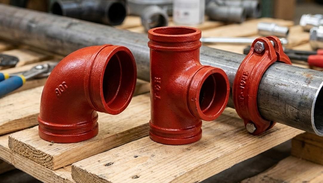
Everything You Need To Know About Grooved Pipe Fittings

If you work anywhere near piping systems, you have probably come across grooved fittings at some point. They show up in fire sprinkler lines, HVAC rooms, water systems and plenty of industrial setups. Yet many people who order or install them still are not fully clear on how they work.

This guide breaks down grooved pipe fittings in plain language, covering what they are, how they are made, the types available, how they compare to threaded and welded joints and where they are used most often.

What Are Grooved Pipe Fittings

A grooved pipe fitting is a mechanical joining system that connects two pipe ends using a groove cut or rolled near the pipe end, a rubber gasket and a metal housing held together with bolts. Instead of welding metal together or cutting threads into pipe, the groove gives the fitting something to grip onto.

The idea was first developed by British engineer Ernest Tribe in the early twentieth century. His invention later grew into the company known today as Victaulic, and the joining method has since become standard practice in piping worldwide.

How Grooved Pipe Fittings Actually Work

The process is simpler than most people expect. The pipe end is first grooved using a roll grooving or cut grooving machine. A rubber gasket is then placed over the pipe end and lubricated slightly to help it seat properly. The coupling housing is positioned over the gasket so its inner edges lock into the groove on each pipe. Bolts are tightened evenly so the housing closes and the gasket compresses to form a tight seal.

As water pressure inside the pipe increases, the gasket actually seals tighter rather than weaker, which is one reason this method is trusted in high pressure systems like fire protection mains.

How Pipe Is Prepared For Grooved Fittings

Grooved pipe is not prepared the same way on every project. Two methods are used and it helps to know how each one affects the pipe before it goes into service.

FeatureRoll Grooved PipeCut Grooved Pipe
How the Groove Is MadePressed into the pipe wallCut away from the pipe wall
Pipe Wall ThicknessStays the sameSlightly reduced
Corrosion ResistanceGenerally betterSlightly lower due to thinner wall
Common UseLighter wall steel pipeHeavier schedule pipe
Interior SurfaceSmall internal ridgeSmooth interior

Both methods are accepted under recognized piping standards, so the right one for a project usually comes down to pipe schedule, application and site conditions.

Common Types of Grooved Fittings

Grooved systems are not limited to straight couplings. A full range of fittings is available to handle almost any pipe run.

  • Grooved couplings, which join two pipe ends together and come in rigid or flexible versions
  • Grooved elbows, available in 90 degree, 45 degree and other angles for directional changes
  • Grooved tees and crosses, used to branch a line in one or more directions
  • Grooved reducers, used to step down from a larger pipe size to a smaller one
  • Grooved caps, used to close off the end of a branch line

For directional pipe changes on the same project, our earlier post on elbow pipe fittings and their applications walks through the different angle options.

Since gaskets are central to how every grooved joint seals, our guide on gasket pipe fittings is also worth a read.

Where Grooved Fittings Fit Among Pipe Joining Methods

Every piping project has to choose a joining method, and each option serves a different purpose on site. Threaded connections work well on smaller pipe sizes but take longer to prepare and carry a higher risk of leaks over time. Welded joints, covered in our post on buttweld fittings and their applications, create an extremely strong permanent bond but require skilled labor and hot work permits.

Grooved fittings sit in a practical middle ground. They install faster, need no open flame, and can be visually inspected simply by checking that the bolt pads have closed properly. This is why they are often the preferred choice on large fire protection and HVAC projects with tight schedules.

Benefits Of Choosing Grooved Fittings

The popularity of grooved systems comes down to a handful of real advantages that matter on site every day.

  • Faster installation compared to welding or threading, which reduces labor hours
  • No hot work permits or open flame needed during installation
  • Easy visual inspection through bolt pad alignment
  • Simple disassembly for maintenance, repairs or system changes
  • Tolerance for minor pipe movement caused by thermal expansion or vibration

These benefits are why grooved systems have become a standard specification item on fire protection and mechanical drawings rather than just an alternative option.

Where Grooved Fittings Are Used Most

Grooved pipe fittings show up across a wide range of industries because they adapt well to different pressures, pipe sizes and environments.

Fire protection systems rely on grooved fittings for both main and branch lines because of the speed and reliability during installation and inspection. HVAC systems use them extensively in chiller plants and mechanical rooms where pipe runs need frequent adjustment. Plumbing and water distribution systems in commercial and industrial facilities also benefit from the reduced installation time.

Material choice matters too. Many grooved systems pair with stainless steel or ductile iron components depending on the environment, and our post on stainless steel pipe fittings explains where that material performs best.

Choosing A Reliable Grooved Fittings Supplier

Not every fitting on the market meets the same manufacturing standard, so sourcing from a supplier who understands certification and application requirements matters. Working with an experienced grooved pipe fittings supplier UAE teams trust helps ensure your project gets fittings rated for the correct pressure and backed by real technical support rather than guesswork.

Before placing an order, confirm the pipe schedule, working pressure and environment of your project so the supplier can recommend the right groove type, gasket material and housing grade for the job.

Conclusion

Grooved pipe fittings have earned their place across fire protection, HVAC and plumbing systems because they solve a real problem, joining pipe quickly and reliably without welding or lengthy threading work. Understanding how roll grooved and cut grooved pipe differ, the fitting types available and how grooved systems fit alongside other joining methods puts you in a better position when planning your next project.

For certified grooved pipe fittings and expert guidance across the UAE and GCC, FW Trading LLC stocks a complete range built for demanding industrial use.

Ready to get started? Reach out to our team today for technical advice or a fast quote.

Expert Guides on Industrial Insights

If you want to deepen your understanding of industrial equipment, material handling, and engineering best practices, explore these related articles.


A Complete Guide to Marine Valve Types and Applications

Every ship depends on a hidden network of valves working around the clock. These components control seawater, fuel, steam and air across the vessel, and choosing the wrong one can lead to costly downtime or safety risks. From the engine room to the ballast tanks, each system relies on a valve built for its own pressure, temperature and flow conditions.

Engineers, ship operators and procurement teams often face the same question when a system is being designed or repaired, which valve actually fits the job. This guide breaks down the main marine valve types, where each one belongs on board and how to pick the right fit for your system.

What Are Marine Valves?

Marine valves are fluid control devices built specifically for shipboard use. Unlike standard industrial valves, they need to handle constant vibration, salt exposure and sudden pressure changes without failing.

On a vessel, valves generally perform three jobs.

  • Controlling the rate of flow through a pipeline
  • Directing fluid to the correct system or tank
  • Isolating a section of piping during repairs or emergencies

Why Marine Environments Demand Specialized Valves

Ships operate in some of the harshest conditions any mechanical equipment will face. Saltwater accelerates corrosion, engine rooms run hot, and constant motion puts extra stress on seals and joints. A valve that performs well on land can fail quickly at sea if it was not engineered for these conditions.

That is why marine valves are built with corrosion resistant materials, reinforced sealing and stricter testing standards than typical commercial valves.

Common Types of Marine Valves and Their Uses

Each valve type is built for a specific job. The table below gives a quick overview before we look at each one in more detail.

Valve TypeOperating MotionBest Suited For
Gate ValveLinear sliding gateFull open or full close isolation
Ball ValveQuarter-turn rotating ballFast shutoff with minimal resistance
Globe ValveLinear plug and seatPrecise flow throttling
Butterfly ValveQuarter-turn rotating discCompact spaces needing quick control
Check ValveAutomatic one-direction flowPreventing backflow into pumps
Safety ValvePressure-activated releaseProtecting pressurized systems

Gate Valves and Ball Valves for Isolation and Quick Shutoff

Gate valves use a sliding gate to fully block or fully allow flow. They offer very low resistance when open, which makes them a common choice for main seawater lines, ballast routing and firefighting mains where a dependable on or off function matters more than fine adjustment.

Ball valves work differently. A quarter turn of the handle rotates a bored ball to open or close the flow path almost instantly. This speed and tight sealing make them ideal for bilge transfer lines, fuel loading systems and remote manifold controls. Engineers who need help comparing these two options in more depth can review this detailed comparison of butterfly and gate valve performance for UAE industrial conditions.

Globe and Butterfly Valves for Flow Control

Globe valves are built for throttling rather than simple shutoff. Their internal baffle and movable disc allow an operator to fine tune flow rate, which is why they show up in engine cooling circuits, lube oil systems and steam lines on tankers with auxiliary boilers.

Butterfly valves take a lighter approach. A rotating disc mounted on a central rod controls flow with a small footprint, making them popular in HVAC chill water lines, ballast systems and engine room seawater intakes where space is limited.

Check Valves and Their Role in Preventing Backflow

Check valves open automatically when fluid flows forward and close the moment it tries to reverse. No manual operation is needed, which is exactly why they matter so much on board. Bilge discharge lines, heat exchanger outlets and fuel transfer systems all rely on check valves to stop backflow that could flood a compartment or damage a pump.

Regular inspection is important here since a stuck check valve can quietly compromise an entire system. For guidance on sourcing dependable units, this overview on choosing a reliable check valve supplier covers the qualities worth checking before you buy.

Safety Relief and Strainer Valves for Marine Systems

Safety and relief valves protect pressurized equipment such as boilers, air compressors and hydraulic units by releasing excess pressure before it becomes dangerous. Marine safety codes require regular calibration and testing of these valves since a failure here can lead to serious equipment damage.

Strainer valves play a supporting role by filtering debris and marine growth out of seawater before it reaches pumps and heat exchangers. Sea chest systems, fire mains and cooling circuits all benefit from this extra layer of protection.

Choosing Valves for High Pressure Marine and Offshore Systems

Offshore platforms, tankers and vessels with high pressure fuel or steam systems place extra demands on valve design. Pressure ratings, temperature tolerance and resistance to corrosive media all need to be checked carefully before installation.

Solenoid operated valves are increasingly used here since they allow automated or remote control for fuel systems, cooling circuits and desalination units. If your project involves demanding pressure conditions, this guide to selecting high pressure valves for oil and gas applications explains the key factors engineers weigh before specifying equipment.

Material Selection for Marine Valves

The material a valve is made from has a direct impact on its lifespan at sea. Below is a quick reference for the most common choices.

MaterialCorrosion ResistanceTypical Marine Use
BronzeVery high in seawaterBallast, bilge, and firefighting lines
Stainless Steel 316High against chloride exposureEngine room and treatment systems
BrassModerate, avoid direct seawaterFreshwater or low-pressure lines
Cast IronLow without coatingHVAC and select ballast applications
Titanium AlloyExtremely highOffshore platforms and naval vessels

Sourcing Reliable Marine Valves

Picking the right valve type is only half the job. Sourcing valves that are manufactured to marine grade standards, tested for pressure and backed by proper documentation is just as important for long term reliability. A trusted marine valves supplier can help match the correct material, pressure rating and connection type to your specific vessel or offshore application.

Conclusion

Marine valves may seem like small components, but they sit at the center of every critical system on a vessel, from cooling and fuel supply to ballast and firefighting. Understanding what each type does and where it belongs helps engineers build safer, more efficient systems and avoid costly failures at sea.

For certified marine valves and expert guidance across the UAE and GCC, FW Trading LLC stocks a complete range built for demanding marine and offshore use.

Ready to get started? Reach out to our team today for technical advice or a fast quote.

Expert Guides on Industrial Insights

For teams sourcing beyond valves, these guides cover other equipment categories that often show up on the same marine and industrial projects.

Top 10 Essential Electrical Components and How to Choose Them

Every electrical installation, whether it is a small residential fit out or a large industrial facility, depends on a handful of core components working together safely. Picking the wrong cable, breaker or fitting does not just cause inconvenience. It can lead to overheating, equipment failure and real safety risks on site.

This guide walks through the ten components every buyer, contractor and facility manager should understand, along with practical tips for choosing the right one for your project.

What Are Electrical Components

Electrical components are the physical parts that make up a circuit or an electrical system. They control how current flows, how power is distributed and how a system stays protected under normal and fault conditions. Understanding what each part does makes it far easier to specify the right product instead of guessing based on price alone.

The 10 Essential Electrical Components

Every safe and efficient electrical system relies on these essential components, each serving a specific role in power distribution, protection, control and connectivity.

1. Cables and Wires

Cables carry power from source to load, so the conductor size, insulation type and installation environment all matter. Copper conductors are common for general wiring because of their conductivity, while armoured cable suits underground or outdoor runs where extra mechanical protection is needed.

2. Switches

Switches control when a circuit is open or closed. Options range from simple one way switches for a single light to two way and intermediate switches for staircases and long corridors. Smart switches are becoming popular for remote or scheduled control in modern buildings.

3. Sockets and Outlets

Sockets need to match the current draw of connected devices and the environment they sit in. Kitchens, bathrooms and outdoor areas usually call for splash proof or weather protected sockets, while standard indoor sockets should still meet recognised safety standards.

4. Circuit Breakers

Circuit breakers protect a system from overloads and short circuits by cutting power automatically. Miniature circuit breakers work well for most standard loads, while units with added earth leakage protection are used where extra safety is required, such as in wet areas or industrial panels.

5. Fuses

Fuses remain a simple and low cost way to protect a circuit. The rating has to be matched carefully to the appliance or circuit it protects. A rating that is too high offers little protection, and one that is too low leads to constant nuisance replacements.

6. Light Fixtures and Luminaires

Beyond appearance, a light fixture needs to match its lamp type, wattage and installation location. Outdoor fittings require a suitable IP rating to resist dust and moisture, and LED options are generally preferred for their lower running cost and longer lifespan.

7. Junction Boxes

Junction boxes protect wire connections from dust, moisture and accidental contact. The box needs enough internal space for the number of wires it holds, and materials should suit the setting, with metal boxes often preferred in industrial areas that need added fire resistance.

8. Conduits

Conduits shield cables that run along walls, ceilings or underground. Plastic conduit is light and easy to install for most domestic work, while metal conduit gives stronger protection in commercial or industrial settings where impact resistance matters more.

9. Relays and Contactors

Relays and contactors are used to switch higher loads or automate control circuits. Matching the coil voltage and the rated current of the device being controlled is essential, and DIN rail mounted relays are a practical choice for control panels.

10. Timers and Sensors

Timers and sensors add automation to lighting, ventilation and other equipment. PIR sensors are widely used for security lighting since they respond to movement, while time switches help cut wasted electricity by turning devices off after a set period.

Component Comparison at a Glance

ComponentMain FunctionKey Buying Factor
Cables and WiresCarry current from source to loadConductor size and insulation type
SwitchesOpen or close a circuitLoad rating and switching type
Sockets and OutletsConnect devices to the supplyCurrent rating and IP protection
Circuit BreakersProtect against overload and short circuitRated capacity and trip type
FusesProtect circuits from excess currentCorrect rating for the load
Light FixturesProvide illuminationLamp compatibility and IP rating
Junction BoxesHouse and protect wire connectionsSize, material and IP rating
ConduitsPhysically protect cablesMaterial and installation environment
Relays and ContactorsSwitch or automate higher loadsCoil voltage and current rating
Timers and SensorsAutomate control of devicesAdjustability and load compatibility

Panels and enclosures that combine several of these parts often sit alongside other industrial materials on the same site, and the same care given to choosing stainless steel pipe fittings for industrial projects should apply when specifying enclosures exposed to moisture or chemicals.

How to Choose the Right Electrical Components

Choosing correctly comes down to asking a few practical questions before placing an order.

  • What is the application, whether domestic, commercial or industrial, and is it indoor or outdoor
  • What voltage and current will the component actually need to handle
  • Does the location call for a specific safety or compliance rating, such as splash proof gear for a bathroom or kitchen
  • Is the supplier able to provide certified products backed by proper technical support
  • What is the realistic budget once installation and long term reliability are factored in

The table below breaks these factors down further for quick reference during procurement.

Buying Factors by Project Type

Project TypePriority FactorsTypical Components Needed
ResidentialSafety, aesthetics, ease of useSwitches, sockets, light fixtures, MCBs
CommercialLoad capacity, compliance, durabilityCircuit breakers, conduits, relays, sensors
IndustrialHeavy duty rating, fire resistance, automationContactors, junction boxes, armoured cable, timers

Getting the specification right at this stage saves time later, particularly on larger projects where a mismatched component can hold up an entire installation. Many of the same principles used when selecting buttweld fittings for UAE construction projects apply here too, since material quality and compliance with recognised standards always come first.

Common Mistakes to Avoid

  • Choosing a component based on price alone without checking its rating
  • Ignoring the installation environment, especially moisture, dust or vibration
  • Mixing incompatible voltage or current ratings between connected components
  • Skipping proper documentation or data sheets before purchase

If a project also involves sealing or piping alongside the electrical scope, it is worth understanding what a spiral wound gasket is and where it is used, as many industrial sites procure electrical and piping components together from the same trusted supplier.

Final Buying Checklist

Before finalising an order, confirm the voltage and current rating, check the IP rating against the installation environment, verify compliance with local safety standards and make sure the supplier can provide technical guidance if questions come up during installation.

Explore our full range of electrical products supplier in Dubai to find certified components suited to residential, commercial and industrial projects.

Conclusion

Choosing the right electrical components is not about picking the cheapest option on the shelf. It is about matching each part to its load, its environment and the safety standard the project demands, so the system runs reliably for years rather than months.

For certified electrical products and expert guidance across the UAE, FW Trading LLC stocks a complete range built for residential, commercial and industrial use.

Ready to get started? Reach out to our team today for technical advice or a fast quote.

Expert Guides on Industrial Insights

If you want to deepen your understanding of industrial equipment, material handling, and engineering best practices, explore these related articles.


Understanding the Difference Between Lifting and Rigging

Anyone working around cranes, hoists or heavy loads has heard lifting and rigging used almost like they mean the same thing. On a busy site they get mixed up all the time, and treating them as one process is where a lot of safety gaps start.

Lifting and rigging are two separate stages of the same job. One prepares the load. The other moves it. Knowing where one ends and the other begins helps supervisors plan safer lifts, helps buyers pick the right gear and helps new workers understand what is happening around them.

What Lifting Actually Means?

Lifting is the physical act of raising, lowering or shifting a load using mechanical force. It is the part of the operation where a crane, hoist or forklift does the heavy work.

A few things define lifting on a job site.

  • It always uses powered or mechanical equipment such as cranes, hoists, jacks or forklifts
  • Every piece of lifting equipment has a rated load capacity that operators must respect
  • Operators need proper training to judge balance, angle and load behaviour during the move
  • Lifting plans usually include load testing and routine equipment checks before use

In short, lifting is the action. It cannot happen safely on its own though, because a load has to be properly attached and balanced first, and that is where rigging comes in.

What Rigging Actually Means?

Rigging is the preparation stage. It covers everything needed to attach a load securely to lifting equipment so it can travel without shifting, swinging or slipping.

A rigger looks at the shape, weight and centre of gravity of the load, then chooses the right combination of hardware to secure it. This includes slings, shackles, wire rope, chains, hooks and spreader bars.

Good rigging practice usually involves the following steps.

  • Assessing the load for weight, shape and balance point
  • Selecting hardware rated for that specific load
  • Distributing weight evenly across attachment points
  • Following a written rigging plan for complex or heavy lifts
  • Inspecting slings and hardware for wear before every use

Rigging is what keeps a load stable once the crane starts moving it. Without correct rigging, even the strongest crane cannot guarantee a safe lift.

Lifting and Rigging Side by Side

The table below breaks down how the two processes differ in practice.

AspectLiftingRigging
Main RoleMoves the load using mechanical forceSecures and balances the load before it moves
Typical EquipmentCranes, hoists, forklifts, jacksSlings, shackles, chains, hooks, spreader bars
Focus AreaLoad capacity and safe operation of machineryLoad distribution and stable attachment
Skill RequiredTrained crane or hoist operatorsTrained riggers who understand load geometry
Timing in the ProcessHappens after rigging is completeHappens before lifting begins

Common Equipment Used in Each Process

Sites rarely use one without the other, and most equipment falls clearly into one category.

Lifting equipment generally includes cranes, overhead hoists, forklifts and mobile elevated platforms, providing the raw force needed to move a load vertically or horizontally.

Rigging hardware includes wire rope slings, synthetic web slings, chain slings, shackles, eyebolts, turnbuckles and load binders, connecting the load to the lifting equipment and keeping it stable throughout the move.

For teams sourcing both categories from one place, a dedicated Lifting and Rigging Equipment Supplier makes it easier to match compatible hardware to your machinery instead of guessing at ratings from different brands.

Why the Two Have to Work Together

A crane rated for ten tonnes is useless if the sling attached to the load is rated for two. Likewise, perfectly rigged cargo will not move anywhere without the right lifting machine behind it.

Every successful lift depends on this handoff. The rigger prepares the load and confirms it is balanced and secured. The lifting equipment then does the actual raising, lowering or transporting. If either step is weak, the whole operation is at risk, regardless of how strong the other side is.

This is why supervisors check both sides of a lift plan, not just the crane specifications. Load weight, sling angle, attachment points and equipment capacity all have to line up before anyone gives the signal to lift.

Where Lifting and Rigging Matter Most?

These two processes show up constantly across heavy industry.

  • Construction sites rely on rigging to secure steel beams and precast panels before cranes lift them into place
  • Manufacturing plants use both for loading and unloading raw materials and finished goods
  • Ports and shipping yards depend on rigging to secure containers before ship cranes move them
  • Oil and gas operations use rigging extensively when transporting equipment to offshore or remote locations
  • Marine operations lean on both when loading heavy components onto vessels, an area closely tied to the systems covered in our article on storm valves in marine industries

In every case, the sequence stays the same. Secure first, then lift.

Choosing the Right Equipment for Your Site

Picking equipment for either process comes down to a few practical checks.

Start with the load itself. Know its weight and centre of gravity, then match rigging hardware to the lifting equipment’s rated capacity, never the other way around.

Certification matters too, since equipment that meets recognised standards gives you a paper trail for audits and a real safety margin on site, a principle we also cover in our post on safety valve insights for UAE industrial processes.

For a full walkthrough of the selection process from load assessment to final positioning, our Ultimate Guide to Lifting and Rigging Equipment breaks it down step by step.

Conclusion

Lifting and rigging are not competing terms. They are two connected halves of the same operation, and understanding where one stops and the other starts makes every lift more predictable and every crew safer on site.

For certified lifting and rigging equipment and expert guidance across the UAE and GCC, FW Trading LLC stocks a complete range built for demanding industrial use.

Ready to get started? Reach out to our team today for technical advice or a fast quote.

Expert Guides on Industrial Insights

If you want to deepen your understanding of industrial equipment, material handling, and engineering best practices, explore these related articles.

The Ultimate Guide to Lifting and Rigging Equipment

Lifting and rigging equipment forms the backbone of safe material handling across construction, oil and gas, marine and manufacturing sites in the UAE and GCC. From slings and hoists to shackles and hooks, every part plays a role in moving heavy loads without risk.

This guide walks through the main equipment types, how to choose the right gear and how to keep it working safely for years.

What Is Rigging and Why It Matters

Rigging means connecting a load to a crane, hoist or winch using the right combination of hardware. It sounds simple, but choosing the wrong sling, shackle or hook is one of the biggest causes of dropped loads and workplace injuries.

When you understand how each part works together, and you buy from a trusted Lifting & Rigging Equipment Supplier, you can plan every lift so it stays smooth, controlled and safe from start to finish.

Types of Lifting Slings

A sling is the direct link between your load and the lifting device. Picking the right one keeps both the load and the people around it safe.

Webbing Slings

Webbing slings are woven from polyester. They are light in weight and gentle on delicate or painted surfaces.

Round Slings

Round slings have a protected polyester core inside a woven cover. They spread the load evenly, which makes them useful for curved or oddly shaped items.

Chain Slings

Chain slings are made from alloy steel. They handle heavy loads, high heat and rough, abrasive conditions well.

Wire Rope Slings

Wire rope slings combine strength with flexibility. They work well on construction sites and in marine settings.

Rigging Hardware and Connectors

Rigging hardware connects the sling to the crane hook and keeps the whole lifting system stable while the load is in the air.

  • Shackles connect slings, wire ropes and hooks together, and bow shackles handle angled loads better than dee shackles
  • Hooks should always include a safety latch to stop the load from slipping free during a lift
  • Eye bolts and swivel hoist rings create a fixed lifting point directly on the load itself
  • Turnbuckles let you fine tune tension and length when a lift uses more than one point

Always check that hardware carries a clearly stamped working load limit. Choosing certified shackles and connectors makes it much easier to match every part to your load and your working environment.

Comparing Common Sling Types

Use the table below to quickly compare sling types and match one to your job.

Sling TypeBest Suited ForKey Advantage
Webbing SlingLight to medium loads, finished surfacesLightweight and gentle on materials
Round SlingCurved or irregular loadsEven load distribution
Chain SlingHeavy duty, high heat environmentsHigh strength and heat resistance
Wire Rope SlingConstruction, mining, marine workStrong and abrasion resistant

Hoists Used in Lifting Operations

A hoist supplies the mechanical power to raise and lower loads again and again, safely.

  • Manual chain hoists work well where power is limited and lifting only happens now and then
  • Lever hoists offer a portable option for pulling or positioning loads at an angle
  • Electric hoists suit sites with frequent lifting, offering speed and precise control
  • Winches help with horizontal pulling tasks alongside vertical lifting gear

How to Choose the Right Lifting and Rigging Equipment

Picking the right gear for a lift is a step by step decision, not a guess. Each factor below affects safety directly.

  • Confirm the exact load weight, shape and centre of gravity before selecting any component
  • Choose a working load limit that sits well above the total load, since sudden movement adds extra force
  • Watch the sling angle, since a narrow angle adds a lot of extra tension to each leg of the sling
  • Match the equipment material to the environment, using stainless steel near the coast and heat rated chain in foundries
  • Make sure every part in the load path has a similar rated capacity, so the whole system stays balanced and predictable

If you are also sourcing connectors for fluid handling, our complete guide to camlock fittings covers that in more detail.

Inspection and Maintenance Best Practices

Even the best rigging equipment can fail if it is not checked and cared for regularly.

  • Inspect slings and hardware visually before every single lift
  • Look closely for cuts, kinks, corrosion, bent pins and worn stitching
  • Store equipment in a clean, dry area away from chemicals and direct sunlight
  • Lubricate chains and wire rope as recommended to prevent rust and stiffness
  • Keep a written inspection log noting dates, findings and any repairs made

Keeping a close eye on component condition matters just as much with lifting gear as it does with other critical industrial parts, an idea we also cover in our guide on safety valve insights for UAE industrial processes.

Common Mistakes to Avoid

  • Using unmarked or uncertified equipment to save on cost
  • Ignoring visible wear because the gear worked fine last time
  • Overloading a sling or shackle to meet a tight deadline
  • Pulling a load at a sharp angle that the hardware was not designed for
  • Skipping routine inspection during busy periods

Check Out the Best Lifting and Rigging Products

Once you know what your lift requires, having the right parts on hand makes the job much easier.

Conclusion

Reliable lifting and rigging equipment protects your workers, your load and your schedule, all at the same time. Choosing the right sling, hardware and hoist for each job, and inspecting it regularly, keeps every lift under control.

For certified rigging equipment and expert guidance across the UAE and GCC, FW Trading LLC stocks a complete range built for demanding industrial use. Ready to get started? Contact us today for technical advice or a fast quote.

Expert Guides on Industrial Insights

If you want to deepen your understanding of industrial fittings, piping systems, and engineering best practices, explore these related articles:

Complete Guide to Camlock Fittings Types Uses and Material Selection

Camlock fittings are among the most trusted quick connect couplings used across industrial fluid transfer systems. Known as cam and groove couplings, they allow operators to join hoses and pipes in seconds without tools or clamps.

From oilfield operations to food processing lines, these fittings deliver a fast, leak free connection that keeps operations moving. This guide breaks down the types, materials, sizes and everything you need to know before you buy.

What Are Camlock Fittings?

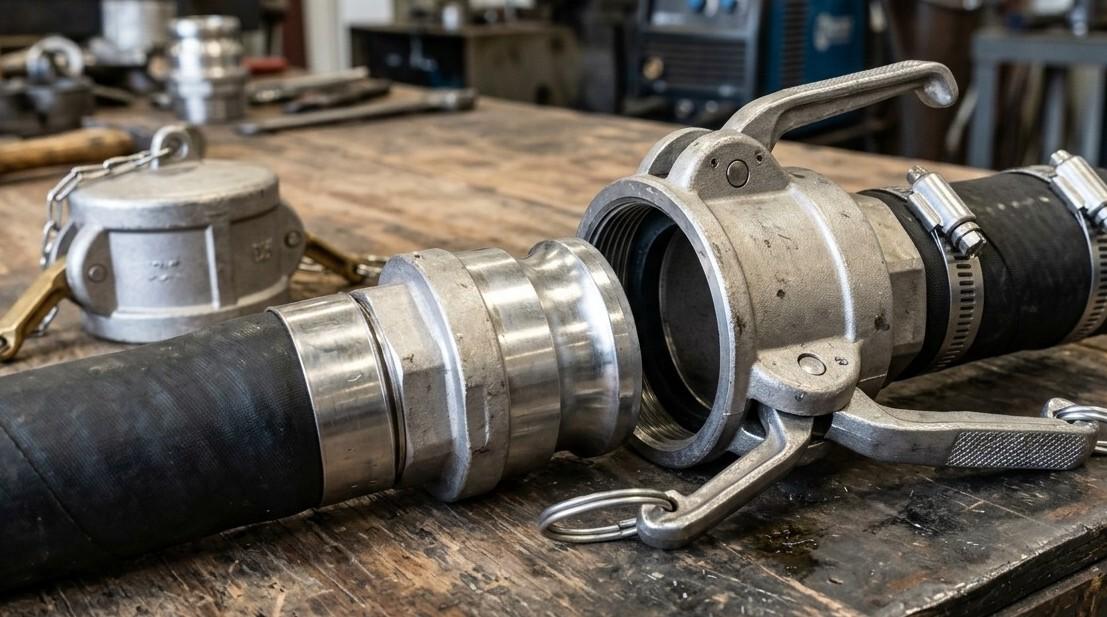
A camlock fitting is a two piece connector made up of a male adapter and a female coupler. The female end has hinged cam arms that lock securely over the groove on the male adapter.

Folding the arms down creates a tight seal in one simple motion. There is no threading, no bolting and no need for specialized tools, which is why these couplings are so popular where hoses are connected and disconnected many times a day.

How Camlock Couplings Work?

The operating principle is straightforward. The male adapter is inserted into the female coupler, and the operator folds the cam arms down into the closed position.

This locks the two halves together and compresses the internal gasket to form a leak proof seal. To disconnect, the arms are lifted and the adapter pulls free, needing only hand pressure and no tools. This same simplicity is why our article on why camlock fittings are ideal for industrial use ranks them ahead of threaded connections for high frequency hose changes.

Types of Camlock Fittings Explained

Camlock couplings are identified by a standardized letter system, from Type A through Type F, along with dust caps and plugs for protection during storage.

TypeConfigurationCommon Use
Type AMale adapter with female threadConnecting to threaded pipe outlets
Type BFemale coupler with male threadConnecting to threaded pipe inlets
Type CFemale coupler with hose tailAttaching to flexible hose ends
Type DFemale coupler with female threadThreaded pipe to pipe connections
Type EMale adapter with hose tailAttaching to flexible hose ends
Type FMale adapter with male threadThreaded to threaded connections
DC and DPDust cap and dust plugProtecting open ends during storage

Matching the correct type to your hose or pipe end is the first step toward a safe connection. Using the wrong configuration is one of the most common causes of leaks in fluid transfer systems.

Choosing the Right Camlock Material

Material selection has a direct impact on how well a camlock fitting performs against pressure, temperature and the fluid being transferred.

  • Aluminium camlock fittings are lightweight and cost effective, making them a strong choice for water, fuel and general purpose transfer
  • Stainless steel camlock fittings offer excellent corrosion resistance and suit chemical, marine and food grade applications
  • Brass camlock fittings handle petroleum products and mild chemicals well and are common in fuel systems
  • Polypropylene camlock fittings resist aggressive chemicals and are a lighter, budget friendly option for agriculture and water transfer

The gasket material also needs attention. EPDM suits water and mild chemicals, Buna N suits oils and fuels, and Viton is the preferred choice for high temperature or aggressive chemical service.

Camlock Size and Pressure Rating Guide

Camlock fittings typically range from half an inch up to six inches. The size chosen should always match the internal diameter of the connected hose or pipe.

Most camlock couplings carry a standard operating pressure rating. Confirm that the fitting you select comfortably exceeds your system’s maximum working pressure and temperature, since undersized or mismatched fittings are a leading cause of pressure loss and premature wear.

Threaded camlock ends also need to match your existing pipework, and NPT and BSP threads are not interchangeable. If you are unsure which standard your system uses, our guide on the difference between BSPT and NPT thread fittings shows how to tell them apart before you order.

Industries That Depend on Camlock Fittings

Camlock couplings are used wherever fluids need to move quickly and safely between hoses, tanks and pipelines.

  • Oil and gas operations rely on camlocks for fluid transfer, tank loading and mud circulation
  • Chemical processing plants use them for tanker loading and temporary maintenance connections
  • Food and beverage facilities depend on stainless steel camlocks for sanitary ingredient transfer
  • Agricultural operations use them for irrigation, spraying and general water handling
  • Construction sites use camlocks for dewatering and dust suppression

Maintenance Tips for Long Service Life

Routine care extends the working life of any camlock coupling and prevents unplanned downtime.

  • Inspect cam arms, gaskets and sealing surfaces regularly for wear or damage
  • Depressurize the system fully before disconnecting any fitting
  • Replace gaskets as soon as cracking or deformation appears
  • Store unused fittings with dust caps or plugs to keep debris out
  • Apply food grade lubricant to cam hinges where recommended to keep movement smooth

Poor installation is behind many of these failures before wear even becomes a factor. Our guide on common installation mistakes that damage industrial fittings covers the errors most likely to shorten a camlock coupling’s service life.

Why Work With an Experienced Camlock Fittings Supplier

Sourcing couplings from a knowledgeable camlock fittings supplier makes selection far easier, especially when a project involves multiple materials, sizes and pressure requirements.

An experienced supplier can confirm chemical compatibility, recommend the right gasket and ensure every fitting meets recognized industrial standards before it reaches your site. This saves time and reduces the risk of costly leaks later.

Conclusion

Camlock fittings remain one of the fastest and most dependable ways to connect and disconnect hoses across oil and gas, chemical, food and agricultural operations. Getting the type, material, size and pressure rating right from the start keeps a fluid transfer system safe and efficient for years to come.

For certified, high quality camlock fittings and piping components across the UAE and GCC, FW Trading LLC supplies a comprehensive inventory tailored to your project’s pressure and material needs. Ready to get started? Contact us today for technical guidance or a quick quote.

Expert Guides on Industrial Insights

If you want to deepen your understanding of industrial fittings, piping systems, and engineering best practices, explore these related articles:

Sign Up to Receive Great Offers!